

For a long time now, I’ve wanted to hack into a boombox, find the audio input on the circuit board and solder an input jack to it. There are so many totally functional boomboxes out there that are useless for those who keep music on an MP3 player. I tried this experiment a few years ago with no success. Now I’m ready to design and build a dedicated recording studio in a spare room of the house, and part of that is coming up with a home-built power amp project. Having only dealt with battery-powered voltages before, I thought I’d give the boombox hack another try–for practice.
My victim was an Emerson FM radio/CD player, bought for $35 at Target in 2004. Once I got it taken apart, I had to isolate the amplifier, which was combined with the FM radio on the same circuit board. After studying the layout I took a shot at analyzing where the division between the radio and amp was. I drew a line, scored it with a blade, and snapped it in half!
Finding the audio input to the amp was pretty easy because the CD player was a separate board and I could just use the points marked “R” and “L” that were wired to the second board. With some alligator clips and an MP3 player I could test if the broken-in-half-board still functioned as an amplifier–and it did.
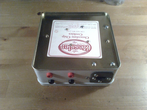
I’m mounting everything inside of a cookie tin almost as if it’s a high-end standalone power amp. It’s not. It operates on 9 volts and outputs 1 watt judging by the specs stamped on the little 3″ speakers. It’ll end up being a funny little desk radio–probably about as loud as your average computer speakers. But I like rehousing things and I really need practice doing chassis work. Despite my attempts at precision, the tin got scuffed up because I was trying to use a dremel and a diamond bit to make the rectangular AC power input. It turned out horribly irregular so I made a plastic one to go over it.
The pictures below show all the components mounted into the tin. It still needs to be wired, painted (since I scuffed it up) and I need to make a lid and speaker enclosures.
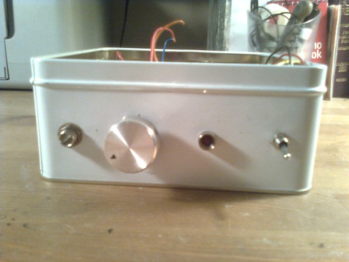
Front panel: input jack, volume control, power LED and power switch
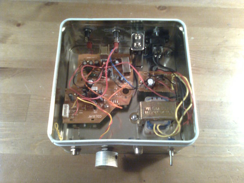
Top view: the large circuit board is the amplifier. Mounted on the right is a 9v battery, the power supply circuit and transformer.
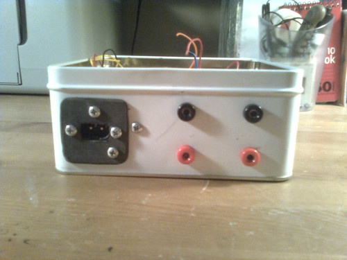
Back panel: AC power receptacle and two banana jacks for each of the right and left speaker outputs.
Bottom view: I mounted the circuit boards using metal standoffs and then I used small nuts and bolts for the transformer.
I just set up this workshop in my basement. If you think the cat pictured here might be yours, sorry but she really likes it here.