

This project incorporated a lot of firsts: my first working circuit powered by mains electricity, my first preamp and the first time I actually took some design initiative — I designed the (very simple) power supply and incorporated a clip detector into the circuit. I opted for a “wall wart” input to supply phantom power for a couple reasons. First, it kept the power supply design simple. Second, it allowed me to eventually use the same supply to get power to multiple preamps, so long as I add the same input jack to all of them.
The preamp design is straight off the INA217 op amp’s datasheet. The clipping indicator design was sourced from the Elliot Sound Products website. I source a lot of my parts from ebay, looking for multiples of the same item so I’m always building an inventory for future projects. As a result, I have no idea how much the total supply cost is. The expensive parts were the transformer ($24) and the case ($12).
Some other design considerations were to use a 1/4″ TRS jack instead of the standard XLR connector. They’re cheaper, and I was intending from the get-go to incorporate the preamp into a patchbay setup. Using a TRS connector doesn’t change its ability to take a balanced line. What it does do, however, is allow the careless user to damage a mic by using a TS cable with phantom power. For the single-engineer home studio this isn’t a problem. It actually gives me a really good excuse to keep my roommate from using my gear.
The op amp’s datasheet does not specify a design for balanced output, and while that may be a minus on a commercial unit, it’s of little consequence to me since the pre will always be in my control rack with about a 3 foot cable run to the audio interface.
I opted for stripboard construction over more compact methods because I just wanted a working, reliable preamp. For me, that requires plenty of soldering room. I actually like the industrial look and size of it. Perfboard irks me to no end and at the time I hadn’t yet worked up to etching.
For the phantom power supply, I found a 48v 375mA wall wart on ebay and rehoused it with a standard output power jack in the front and a standard mains IEC connector in the back. To get the power to the pre, you can use a run-of-the-mill pedal daisy-chain cable. With microphones typically consuming 10mA of power tops, there’s plenty of capacity in this supply.
Circuit design sources:
- ina217 datasheet
http://www.ti.com.cn/cn/lit/ds/symlink/ina217.pdf - Elliot Sound Products – Project 146
http://sound.westhost.com/project146.htm
Schematic:

Stripboard Layout:
The schematic for project 146 specified a pot between pins 2 and 5 of the TL072, and in the notes, it is recommended that the pot be replaced with a 10k resistor for fixed-gain applications so I ended up going for the 10k resistor.

I had a hard time finding the right pot, but in the end — contrary to what’s recorded in the schematic — I went with a 2.5k reverse-log taper.
Build Photos:

Designing the circuit board.
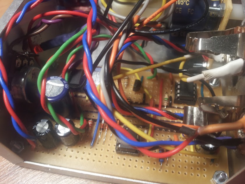
Building the circuit board.

Putting the box together.

Rehousing the phantom power adapter.

Label of the phantom power adapter specs copied from the original housing.

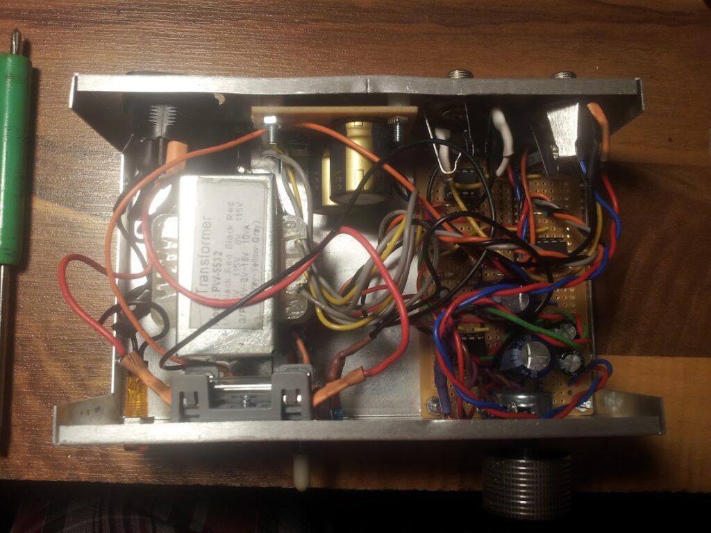
The transformer.

Power supply detail.

Installed circuit detail.
Power section all put together.

Open box with front panel.

Open box with rear panel.

Top View

Finished Preamp:
Front panel: Pilot light, +48v input, phantom power switch, phantom power indicator, clip indicator, gain pot.

Rear panel: Input (TRS), Output (TS), power on/off switch, mains power jack.

Hooked up and powered on.

In the rack.

This pre definitely holds its own alongside the stock preamps in my interface, which was exactly what I wanted: simply more channels of clean gain. Considering the ART TubeMP retails at about $50, this maybe wasn’t the cheapest option. On the other hand, the DIY build is more elegant, not to mention repairable — should something go wrong.